The CANADUINO® ES100 ADK V2 is a refreshed and improved version of the original EverSet ES100 WWVB-BPSK Atomic Clock Application Development Kit for the 60kHz clock radio signal from Fort Collins, Colorado (USA).
The ADK V2 is based on the same proven ES100 technology and remains software-compatible with the original design. The update includes several PCB corrections, a new Arduino library, significantly improved demo firmware, and updated documentation.
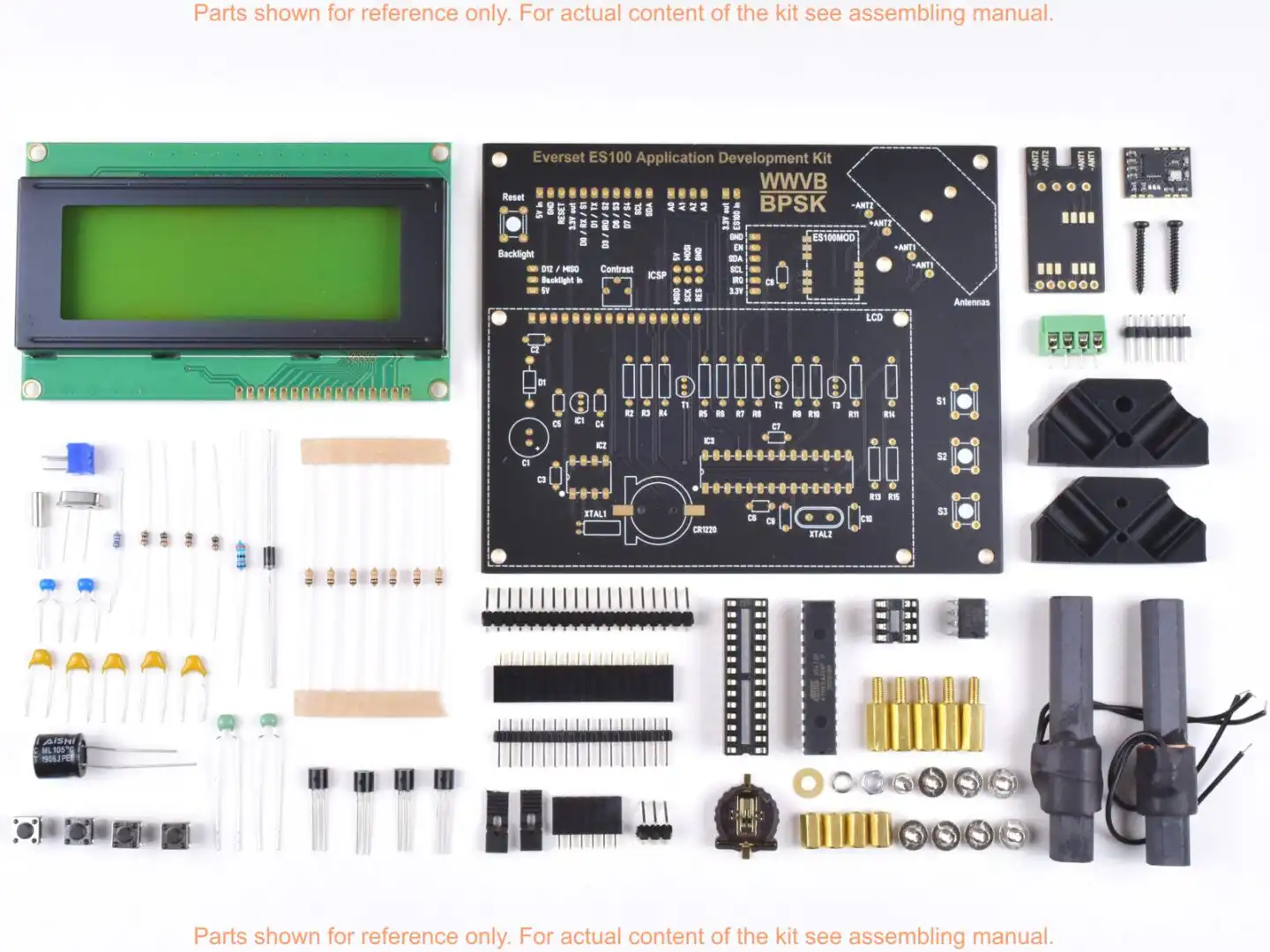
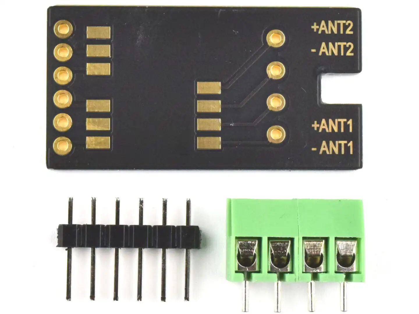
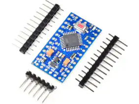
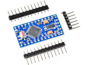
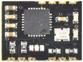
The kit includes the bare PCB and all electronic components required to assemble the device as shown in the product images. It contains one EverSet ES100MOD atomic clock receiver module and a matching carrier board. The ES100MOD can either be soldered directly onto the ADK PCB or mounted onto the carrier board and connected to the ADK PCB using a pin header, depending on the preferred assembly method.
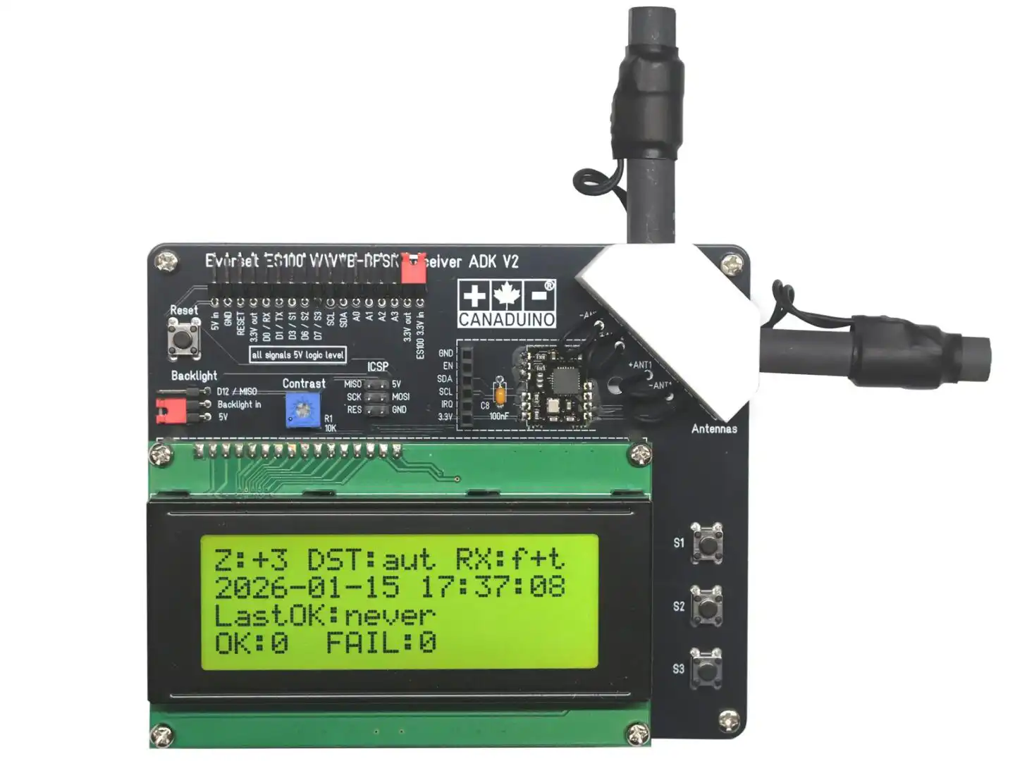
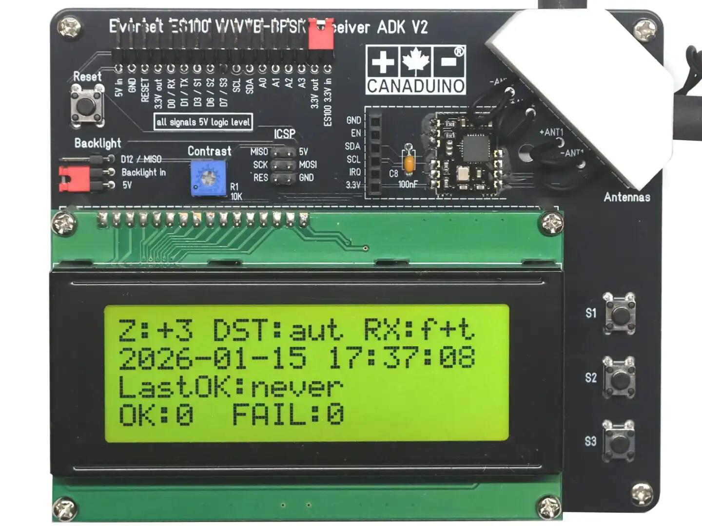
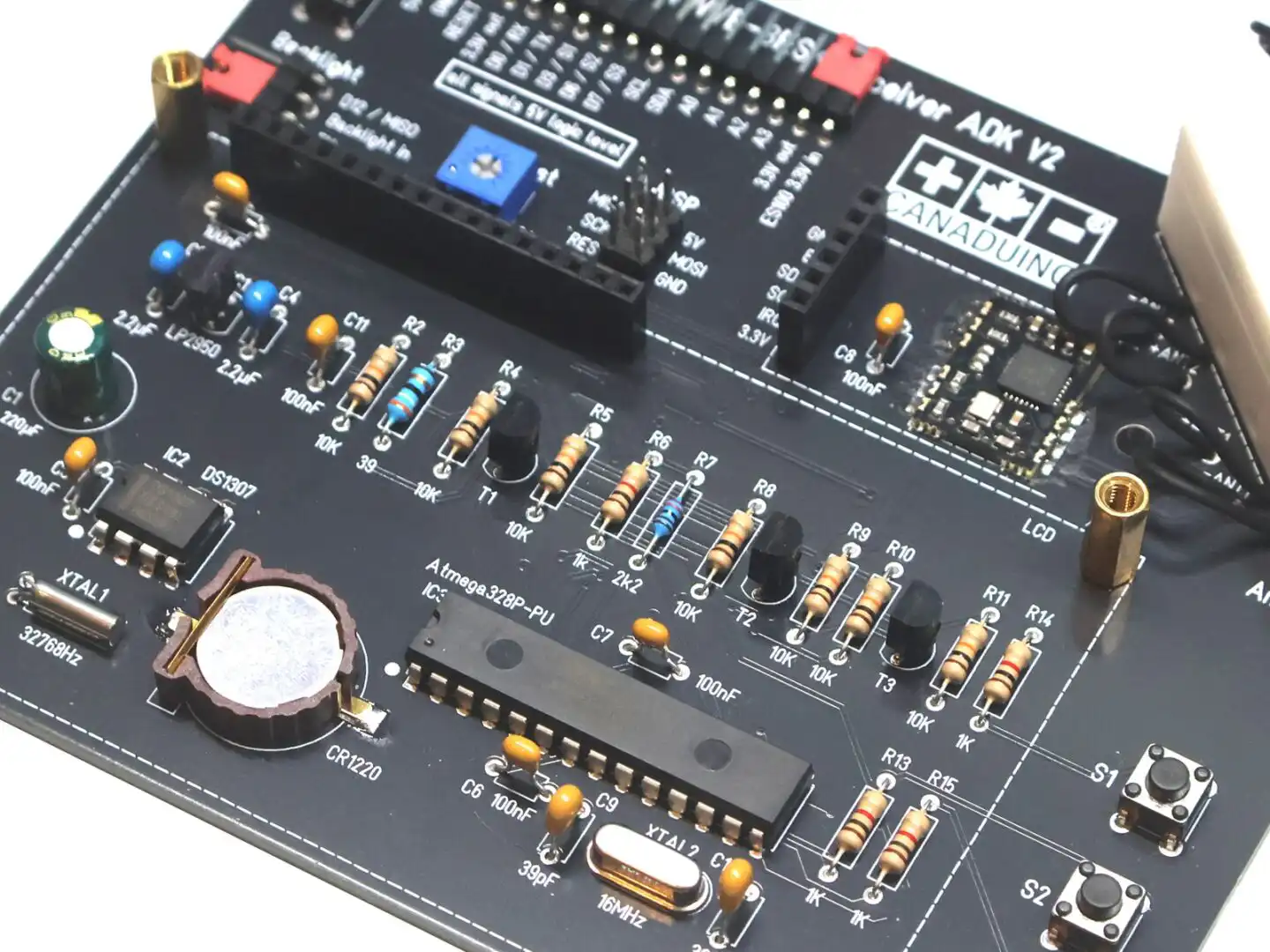
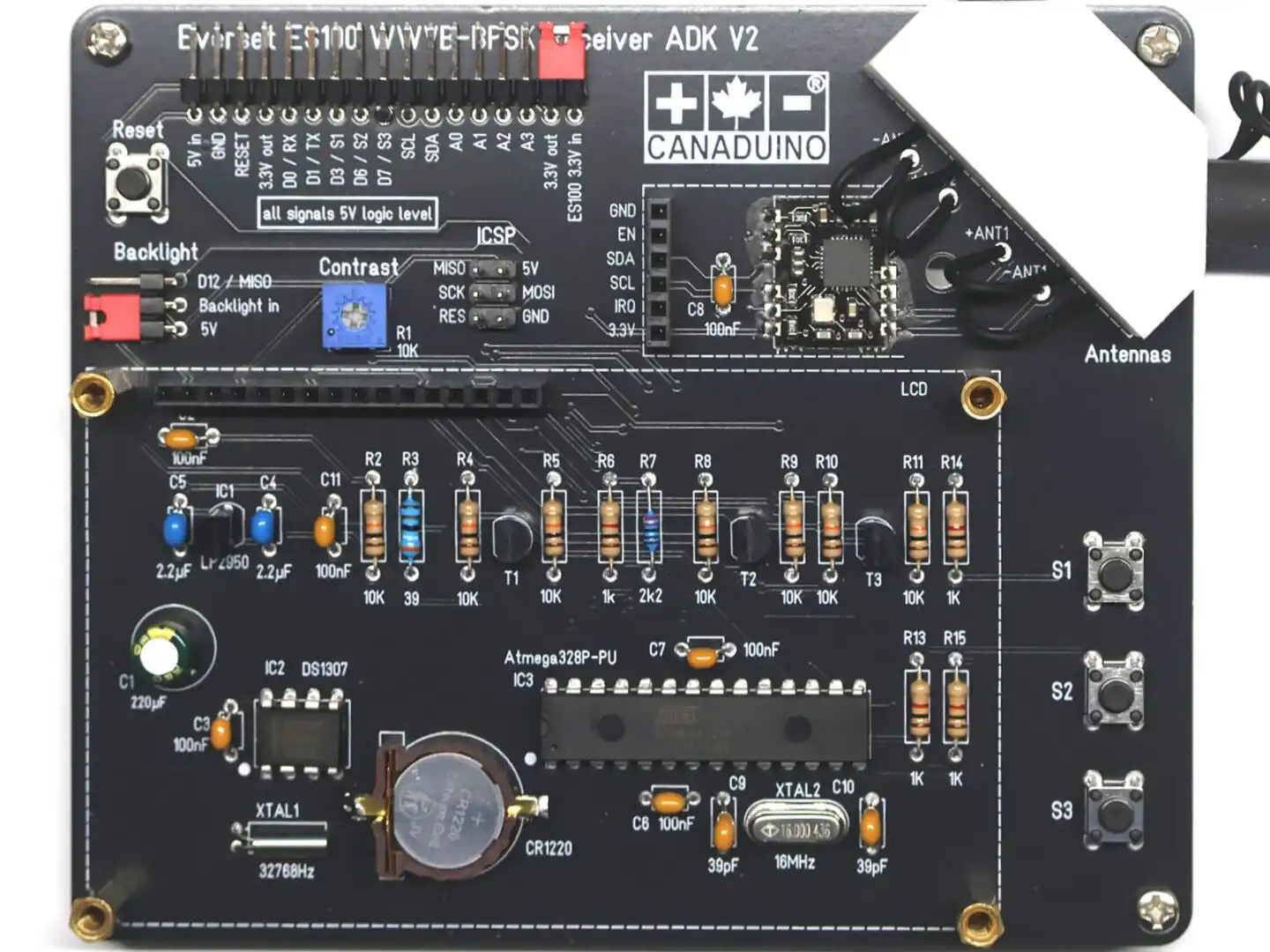
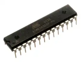
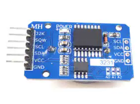
The CANADUINO® ES100 ADK V2 features a 20×4 character LCD, two fine-tuned 60 kHz antennas with an antenna holder, a DS1307 real-time clock (RTC) with backup battery, and an Arduino-compatible ATmega328 microcontroller. The microcontroller is pre-programmed with a comprehensive demo firmware.
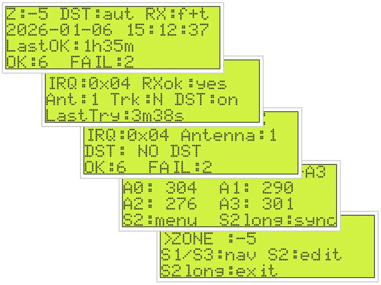
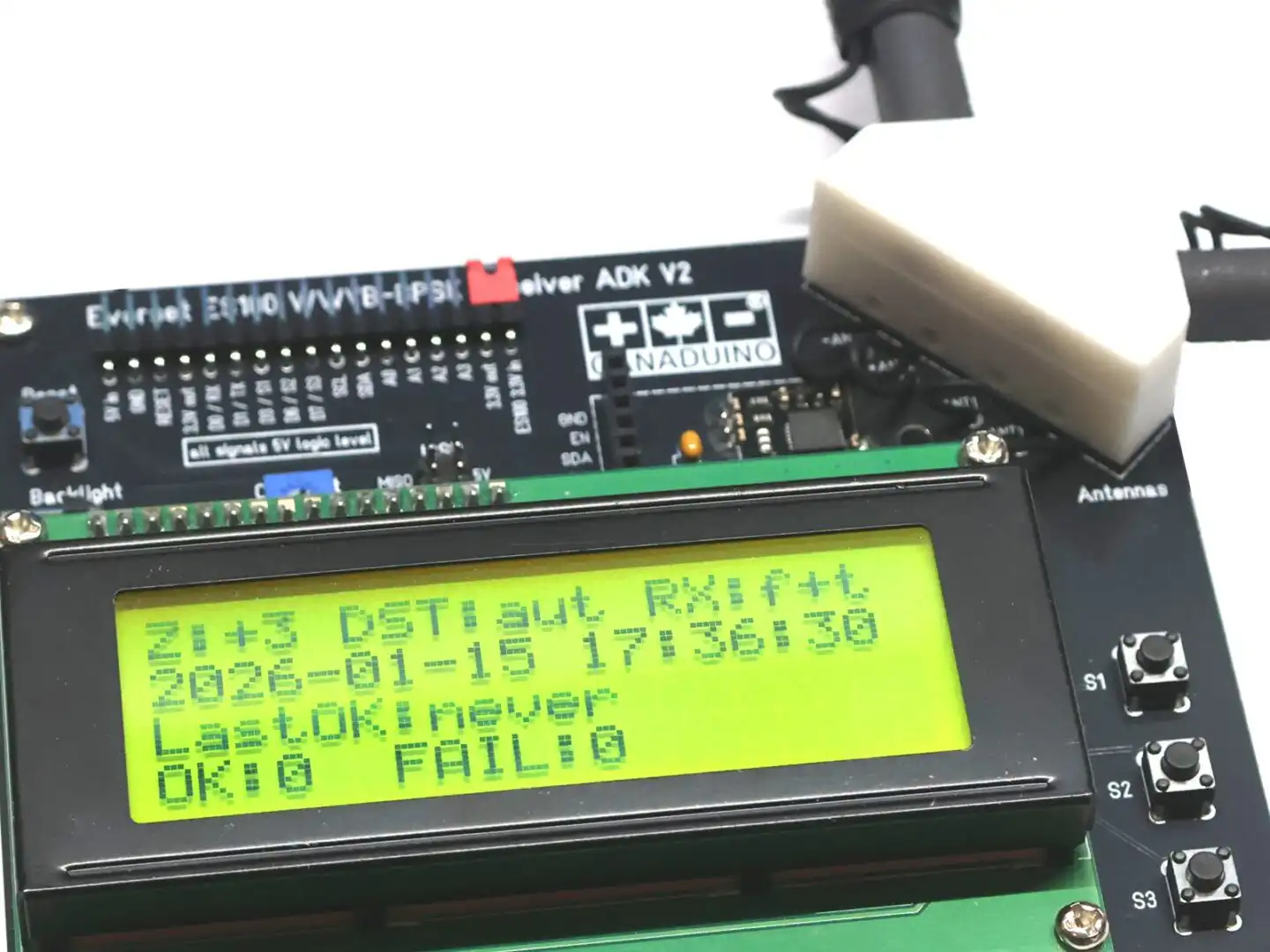
After assembly, the development kit operates as a high-precision atomic clock. The display presents detailed status information including time, date, current DST state, upcoming DST changes, the antenna used for synchronization (1 or 2), and reception diagnostics such as synchronization attempts and decoding status. A detailed explanation of all screens and displayed information is provided in the accompanying PDF manual.
The demo firmware (included in the ES100 V2 library) is heavily commented and designed as a technical reference. It explains the complete interaction between the ES100 receiver, RTC, display, and user interface, making it suitable as a starting point for custom firmware development or for creating entirely new applications.
Important notes:
- This product is intended as a development and evaluation tool for embedded systems designers, software engineers, and technically inclined hobbyists. It is not designed as a consumer-grade, maintenance-free clock for everyday household use.
- Educate yourself about the signal coverage. A map and explanations about reception and coverage are available on NIST official website and on Wikipedia, for example.
- The included antenna holder is not a perfect design, but it is a space saving solution that works acceptable in most situations. You can increase RX performance if you keep the antennas at least 30mm away of each other at the closest point, and align them perpendicular like T rather than L.
Specifications:
- Platform: Arduino UNO compatible
- Processor: ATmega328P-PU, 16MHz (5V)
- Power Supply: 5V, <100mA
- RTC: DS1307 with backup battery CR1220
- I/O: 6 x GPIO (2 of them for serial communication), 4 x analog in, ICSP
- Buttons: 1 x reset, 3 x user definable
- Display: 4 x 20 character LCD with backlight (5V)
- On-Board 3.3V voltage regulator for ES100MOD
- On-Board Level Shifter 3.3-5V
Interesting projects making use of the ES100 WWVB receiver module:
ES100 with Raspberry Pi and Python by Martin Levy
ES100 WWVB reference clock by fiorenzo1963
ES100 WWVB receiver with Arduino DUE (ARM Cortex-M3)
WWVB Receiver with Arduino in-depth project description by Keith Greiner
Code and document downloads:
CANADUINO® ES100 ADK V2 manual (no assembling instructions)
CANADUINO® ES100 ADK V1 manual (with assembling instructions) *
PCB Position Print
CANADUINO® ES100MOD Receiver Module datasheet (PDF)
EverSet ES100 Datasheet
Arduino library V2 including demo firmware V2
* assembling instructions are basically identical for V1 and V2
Substitute parts in DIY soldering kits:
Always install all matching parts first. If you have parts left that are no exact matches to the parts in the schematic, we shipped your kit with substitutes that replace currently unavailable parts. For example: Instead of a 220µF capacitor, some kits come with a 470µF capacitor.
ve7gcr (verified owner) –
Absolutely great kit, definitely a five star package. More than an Application Development Kit, a Skills Development kit as well. Built my first superheterodyne transmitter/receiver a few years back when tubes and discrete components were the parts of choice. The ES100 kit has taken me from the “knob and tube” era to the IC world of Arduino.
It took a few days (a few hours each day) to assemble. Documents, schematics and pictures were very easy to follow. Powered the unit up with a breadboard power supply, and got a signal after 286 interrupts (overnight) in my radio room. Swapped the 328PU in the ES100 with one in a UNO. Made some basic sketch changes (time zone and refresh time) and replaced the processor. Plugged in a 9 volt battery to the power supply and packed the unit over to a south facing window. Sync’s in 2 interrupts. Checked Google maps, and WWVB transmitter is 1,780 km SSE. I regularly use the 2.5, 5, 10, 15 & 20 MHz signals to check signal strength, antenna and tuner. Next step, try ICSP to make changes to the sketch in the 328PU.
Started by searching the internet only to find a million different ways to setup an ISP programmer. Settled on one that seemed to make sense. Built the circuit, putting in a capacitor between the ground and reset pins, double checked the wiring, and set up the blink sketch to transfer between two UNO’s via the ICPS pins, clicked upload, and voila , lights flashed and two instant bricks were created (salvaged them later). Bootloaders were scrambled (without toast). Biggest stumbling block was the boards on my 1.8.2 version of the IDE were not up to date (using Windows 7). NOTE: the Arduino reference for ISP is correct, but misleading, the bootloader part is not needed to do a sketch upload.
With my UNO’s out of commission, a NANO became my ISP programmer and had robbed another UNO for the 328PU, got the 328PU programmed using the ICSP pins. With a dud 328PU in the ES100, the total current draw was just over 50ma, so minor care is needed to supply the ES100 so no GPIO should exceed 40ma or 250ma for the programmer.
Next part of the Application Development; UART communications to another device, first by wire, then using wifi to sync data loggers and some home automation projects.
Would recommend a clear straightforward step by step for the Arduino ISP, with no discussion about bootloaders. A pdf document with the kit documentation would be useful for us novice Arduino developers. Live and learn.
Definitely ⭐️⭐️⭐️⭐️⭐️…….
Greg R VE7GCR, BC Canada.
wa3etd (verified owner) –
Outstanding kit! Assembly is painless if one has basic soldering skills and a good soldering station.
My only nit is that several of the caps provided were alternately sourced and didn’t match the footprint on the PCB – minor.
Note that the clock does not immediately start timekeeping, even with a good 60 kHz signal. The initial display presents two lines of info and incorrect time. My clock took about 5 minutes to lock, which allows all data to be presented.
I highly recommend this kit – the main PCB is high quality and silkscreened.
wa3etd (verified owner) –
This is my second “review” of this outstanding module. Regarding the provided demo program, I have comments that can be ignored by anyone not interested in modding the demo. Much of the following was discovered when porting the code to an Arduino DUE (3.3V I/O), eliminates the need for three level converters The following applies to the stock demo program.
1. Any additional variable added will be corrupted by an array dimensioned incorrectly.
In char * getISODateStr()
{
static char result[21]; // Was 19, which is a bug. Array was too small. FIX THIS
———————————————————–
2. Scrolling display flickers when viewing off boresight. The three scrolling rows are precleared every cycle by writing
20 spaces in each row prior to the desired data. LCD writes are expensively slow. The fix is to eliminate the
clearing – eliminate the clearLine(20); statement at each case. Then, pad each of the optional scrolling fields to
exactly 20 positions. For example, (snip)
case B11:
lcd.print(“Pos. LS this month “); // pad to 20
break;
—————————————————–
3. Although code is present, the program will never update the RTC after the initial signal capture. This is due to the
actual TOD not being updated for the comparison to the user provided update time. This can be cured by
capturing the actual time each cycle in function char * getISODateStr() and using that for the update test.
——————————————————————–
4. Note that the three pushbuttons are incorrectly called out on the silkscreen. The schematic is correct, the labeling
is incorrect.
As mentioned, the demo ported to the DUE with no issues. I used a DS3231 clock module instead of the ‘1307, and a
I2C liquid crystal display to save interconnects. I2C LCDs are even slower that direct wired displays, which emphasized the scroll flicker – totally resolved by the above fix.
Hopefully this will help some, and encourage others to “get into the code”. Fun project all around!