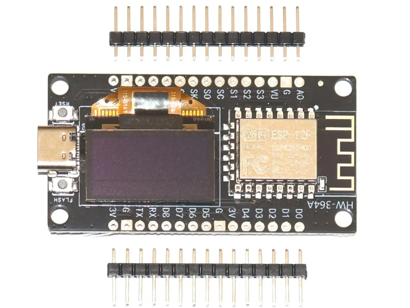
This module combines an ESP8266 WiFi development board with a built-in 0.96 inch OLED display on one compact PCB. It is designed for IoT projects, wireless sensors, small data displays, clocks, status panels and other applications where you want both a microcontroller and a screen without extra wiring.
Compared with a standard ESP8266 development board, this version already includes the display, which saves space and makes prototyping much easier. You can power and program the board through USB and display text, numbers, symbols or simple graphics directly on the integrated OLED.
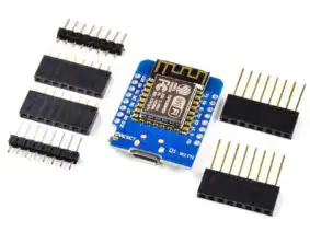
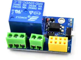
The module fits our Universal Screw Terminal Adapter which can even be mounted to standard DIN rail.
Main features
- ESP8266-based WiFi development board
- Integrated 0.96 inch OLED display
- OLED resolution: 128 x 64 pixels
- Driver IC: SSD1306
- Onboard USB to serial interface for programming
- 4 MB flash memory
- Compact size for embedded and IoT applications
- Suitable for Arduino IDE and other ESP8266 development environments
Technical data
- Microcontroller: ESP8266 / Tensilica Xtensa LX106, 32-bit
- Clock speed: 80 MHz
- Flash memory: 4 MB
- SRAM: 64 KB
- Working logic voltage: 3.3V
- Recommended input voltage: 5V via USB
- Digital I/O pins: up to 16 (depending on pin availability and onboard functions)
- Analog input: 1 x ADC
- UART: 1
- SPI: supported
- I2C: supported
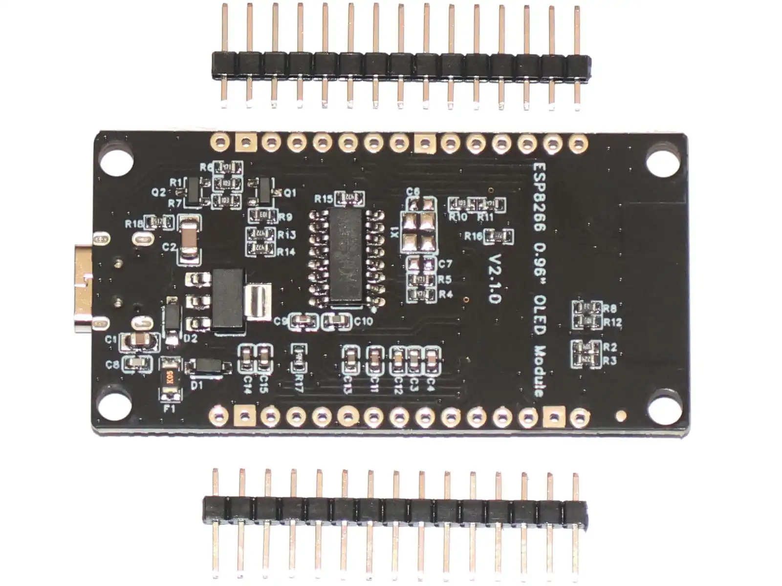
- USB to serial chip: CH340G
- Board size: approx. 59 x 31 mm
OLED display details
- Display size: 0.96 inch
- Resolution: 128 x 64 pixels
- Display controller: SSD1306
- Interface: I2C
- Wide viewing angle
- Self-emitting OLED technology, no backlight required
- Typical display color: blue or yellow/blue, depending on batch
Important note about the built-in display connection
The OLED display is already connected internally to the ESP8266 through the I2C bus. This means you do not need to wire the display yourself.
The display uses the ESP8266's I2C interface internally. On boards of this type, the exact internal pin assignment can vary slightly depending on the board revision, so if you are writing your own code, you should verify the I2C pins used by your specific version or run an I2C scanner if needed. Typical GPIO ports are 12 and 14.
Typical applications
- WiFi sensor display
- NTP clock or weather station
- Smart home control panel
- Small diagnostic or status display
- Portable IoT devices
- Wireless data logger
Getting started
You can program this board in the Arduino IDE using the ESP8266 board package. For the display, use a common SSD1306 OLED library such as Adafruit SSD1306 or U8g2. Because the display is already integrated, setup is simpler than with separate modules.
Typical workflow:
- Install the ESP8266 board support in Arduino IDE
- Install an SSD1306-compatible OLED library
- Select the correct COM port and board type
- Upload an example sketch for the OLED display
- Adjust the I2C address and pin settings if required by your board version
Important notes
- The ESP8266 itself is a 3.3V device
- Use the USB connector for easiest power supply and programming
- Do not apply excessive voltage directly to logic pins
- The OLED is made of glass and should be protected from mechanical stress
- Specifications and board layout may vary slightly depending on production batch
Package contents
- 1 x ESP8266 board with integrated 0.96" OLED display
- 2 x pin header strips
David Villeneuve (verified owner) –
Information on the board is found at https://github.com/peff74/esp8266_OLED_HW-364A. I believe that the SCL and SDA lines are reversed even from what this article says. I found that the OLED display was interfering with the wifi when using ESPHome to code. The solution was to change the I2C frequency to 100 kHz and power-cycle the board. https://github.com/esphome/issues/issues/1329.
Also note that the board is wider than most ESP8266, so it cannot be used on a breadboard.
Otherwise the board behaves just like a ESP8266, but with an on-board display.