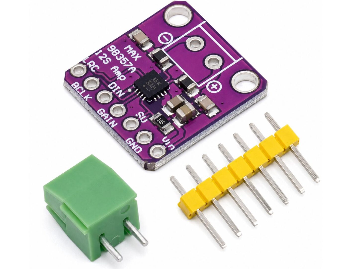
This MAX98357 Class-D Amplifier module is a compact mono Class D amplifier board for microcontroller and single-board computer audio projects. It accepts digital I2S audio directly and drives a small speaker without requiring an external DAC or analog pre-amplifier stage.
The module is suitable for ESP32, Raspberry Pi, Arduino-compatible boards with I2S output, RP2040 boards, and other microcontroller platforms that can generate standard I2S audio signals. It is commonly used for voice output, sound effects, small speakers, audio prompts, internet radio projects, handheld devices, and embedded audio applications.
The MAX98357 Class-D Amplifier chip supports plug-and-play I2S operation, does not require a separate master clock signal, and can automatically work with common PCM audio clock configurations. The module includes solder pads for digital audio input, power, gain selection, shutdown/channel selection, and speaker output.
Typical applications
- ESP32 I2S audio projects
- Raspberry Pi audio output
- Microcontroller voice and sound effect projects
- Small mono speaker amplifier
- Internet radio and streaming audio projects
- DIY Bluetooth or WiFi speaker projects
- Embedded audio prompts and warning sounds
- Portable electronics and handheld devices
- Educational audio and microcontroller experiments
Key features
- MAX98357A digital input Class D mono amplifier
- I2S digital audio input
- No external DAC required
- No MCLK signal required
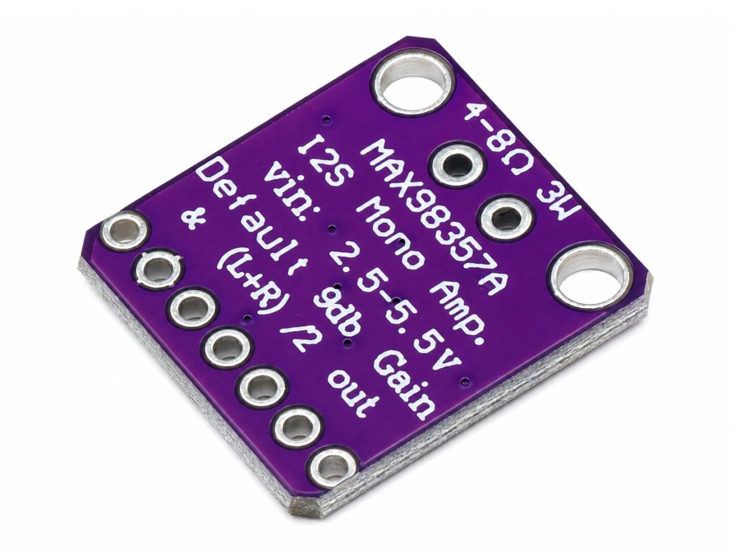
- Single-supply operation from 2.5V to 5.5V
- Up to 3.2W output power into 4Ω at 5V and 10% THD
- Up to 1.8W output power into 8Ω at 5V and 10% THD
- Supports common I2S sample rates from 8kHz to 96kHz
- Class D efficiency for low heat generation and good battery-powered performance
- Selectable gain options
- SD pin supports shutdown and audio channel selection
- Can be configured for left channel, right channel, or mixed mono output
- Stereo output can be built with two modules, one configured for left channel and one configured for right channel
- Integrated short-circuit and thermal protection in the amplifier IC
- Compact module with mounting holes
- Includes screw terminal and pin header parts for flexible connection options
Technical specifications
| Main IC | MAX98357A |
| Amplifier type | Digital input Class D mono amplifier |
| Audio input | I2S / PCM digital audio |
| Output type | Mono differential speaker output |
| Supply voltage | 2.5V to 5.5V |
| Typical logic compatibility | 3.3V and 5V microcontroller systems |
| Output power at 4Ω | Up to 3.2W at 5V, 10% THD |
| Output power at 8Ω | Up to 1.8W at 5V, 10% THD |
| Sample rate range | 8kHz to 96kHz |
| Master clock | Not required |
| Gain options | 3dB, 6dB, 9dB, 12dB, or 15dB, depending on GAIN pin configuration |
| Channel selection | Left, right, or mixed mono, depending on SD pin configuration |
| Speaker connection | Differential speaker output, marked + and - |
| Operating temperature of IC | -40°C to 85°C |
Pin description
| Pin | Description |
| LRC | Left/right clock input for I2S audio |
| BCLK | Bit clock input |
| DIN | Digital audio data input |
| GAIN | Gain selection input |
| SD | Shutdown and audio channel selection input |
| GND | Ground |
| VIN / VCC | Positive power supply, 2.5V to 5.5V |
| + / - | Differential speaker output |
Connection overview
| Module signal | Connect to |
| VIN / VCC | 2.5V to 5.5V power supply |
| GND | System ground |
| BCLK | I2S bit clock from microcontroller |
| LRC | I2S left/right clock from microcontroller |
| DIN | I2S audio data from microcontroller |
| + and - | Speaker terminals |
Channel selection and stereo use
The MAX98357A is a mono amplifier, but it can choose which part of a stereo I2S signal it plays. The SD pin is used both for shutdown and for selecting the audio channel. This allows one module to play mixed mono, left channel only, or right channel only.
| SD pin condition | Function |
| Connected to GND | Shutdown / amplifier off |
| SD voltage approximately 0.16V to 0.77V | Mixed mono output, left/2 + right/2 |
| SD voltage approximately 0.77V to 1.4V | Right channel output |
| SD voltage above approximately 1.4V | Left channel output |
For a stereo setup, use two amplifier modules. Both modules receive the same I2S signals from the microcontroller. Connect BCLK, LRC, DIN, VIN, and GND in parallel to both modules. Then configure the SD pin differently on each module so that one module plays the left channel and the other module plays the right channel.
| Stereo setup | Configuration |
| Left speaker module | Configure SD for left channel output |
| Right speaker module | Configure SD for right channel output |
| I2S signals | BCLK, LRC, and DIN are shared by both modules |
| Power | VIN / VCC and GND are shared by both modules |
On many breakout modules, the SD pin voltage is set with a pull-up resistor or solder jumper. The exact resistor values can depend on the module design and supply voltage. Common module examples use a direct pull-up for left channel selection and a resistor of approximately 330kΩ to 470kΩ to VCC for right channel selection. Some modules are configured by default for mixed mono output.
Gain selection reference
| GAIN pin configuration | Amplifier gain |
| 100kΩ to VCC | 3dB |
| Connected to VCC | 6dB |
| Unconnected / floating | 9dB |
| Connected to GND | 12dB |
| 100kΩ to GND | 15dB |
Notes
- This is a digital I2S amplifier module and is not intended for direct analog audio input.
- The speaker output is differential. Do not connect either speaker output terminal directly to ground.
- For best output power, use a suitable 5V power supply and a speaker with appropriate power rating.
- At lower supply voltages, the available output power will be reduced.
- A single module can play mono audio from a stereo I2S signal by mixing left and right channels.
- For stereo audio, two modules are required. One module must be configured for left channel output and the other module for right channel output.
- The SD pin must not simply be treated as a normal enable pin if channel selection is required.
- The exact pin label may vary between VIN and VCC depending on board revision, but both refer to the positive power input.

Reviews
There are no reviews yet.