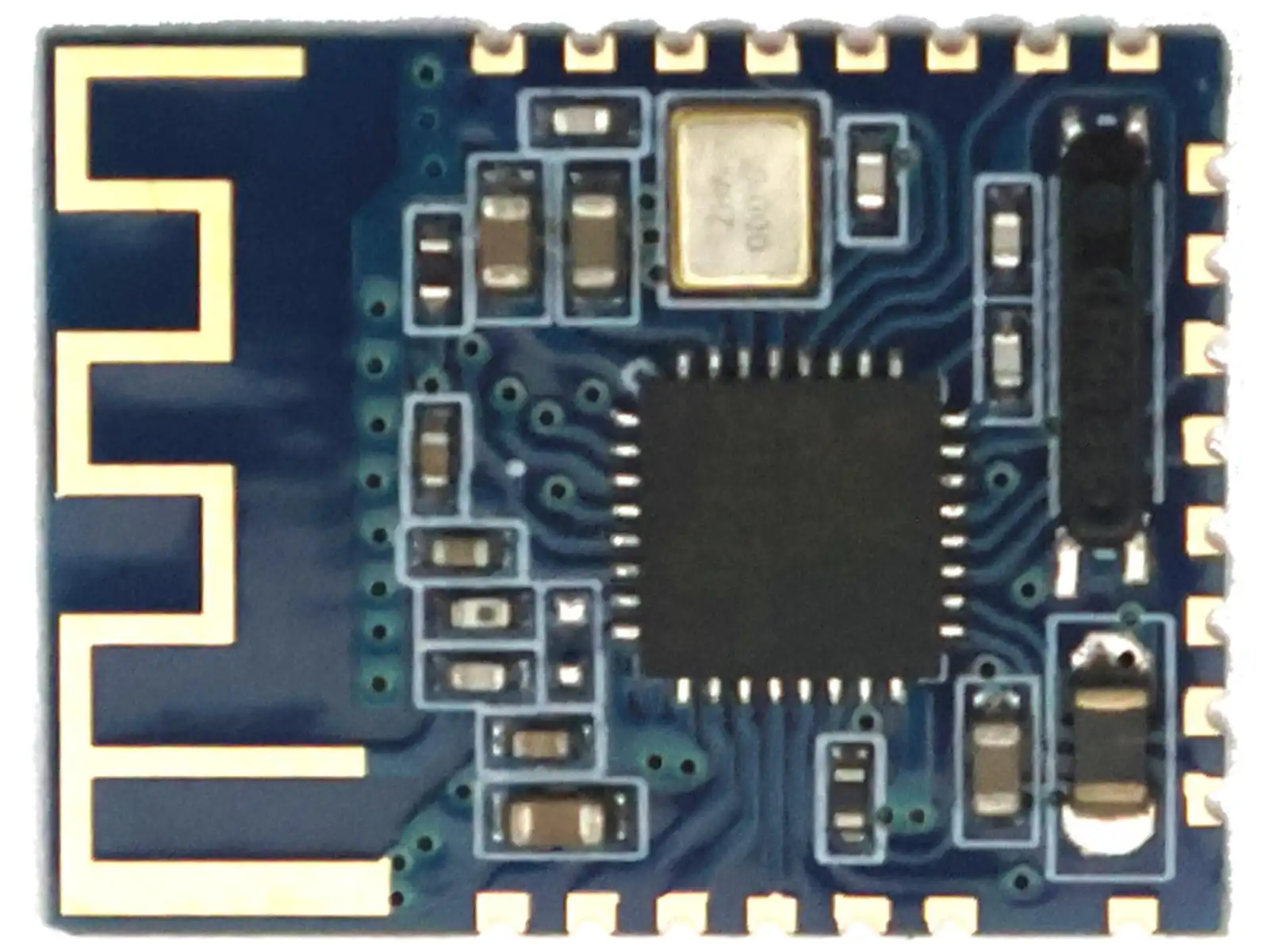


The JDY-16 is a compact (only 20 x 15mm) Bluetooth Low Energy wireless module for low-power embedded communication. It supports both UART and I2C communication modes and offers far more than simple transparent serial passthrough. Depending on firmware configuration, the module can be used for wireless serial communication, app-controlled I/O, PWM control, RTC-related functions, BLE advertising, and master/slave communication.
This module is especially interesting for designers who need a small BLE module that can work either as a classic serial wireless bridge or as a more tightly integrated peripheral controlled by registers over I2C.
Please find the pinout and basic wiring information for serial mode and I2C mode in the image gallery.
Key advantages
- Bluetooth Low Energy communication for low-power wireless applications
- Supports UART and I2C communication modes
- Supports master and slave operation
- Transparent transmission mode
- Continuous sending and receiving supported up to 115200 baud according to vendor documentation
- Effective communication distance stated as up to 80 meters under suitable conditions
- Very low power consumption compared with older Bluetooth serial module families
- Supports I/O control, PWM, RTC, advertising configuration, and app communication
- Supports low-power sleep and wake-up modes
Product overview
The JDY-16 firmware supports functions such as transparent data transmission, wireless app communication, 4-channel I/O control, PWM output control, RTC-related functions, BLE advertising configuration, master/slave communication, and multiple sleep modes.
Main technical parameters
| Parameter | Value |
|---|---|
| Wireless type | Bluetooth Low Energy |
| Operating voltage | 1.8V to 3.3V |
| Operating temperature | -40°C to +80°C |
| Communication interfaces | UART and I2C |
| Communication rate | Up to about 8 KBytes per second |
| UART continuous transceiver | Up to 115200 baud according to vendor documentation |
| Effective communication distance | Within about 80 meters under suitable conditions |
Firmware functions
- BLE high-speed through transmission, supporting about 8 KBytes communication rate
- Supports 3 working modes (see sleep / startup modes below)
- Supports serial port, I/O and app wake-up related functions
- Supports 4-channel I/O port control
- Supports high-precision RTC-related clock functions
- Supports PWM functions controllable through UART, I2C and app-related control
- Supports UART and I2C communication modes, default is UART mode
Electrical characteristics
| Working mode | Broadcast state | Typical current | Remarks |
|---|---|---|---|
| Wake up | Broadcast | 4mA | General communication with app connection |
| Deep no broadcast sleep | No broadcast | 1.38uA | Very low sleep current |
| Light sleep broadcast | 100ms broadcast interval | 280uA | Average current depends on advertising interval |
| Average power consumption | 200ms broadcast interval | 140uA | Recommended broadcast interval is generally 100ms to 500ms |
| Average power consumption | 300ms broadcast interval | 80uA | Longer intervals reduce average current |
| Wake up state | Connected | 4mA | Connected communication state |
| Sleep state | Connected | 50uA | Sleep in connected state possible depending on mode |
Broadcast interval affects both response speed and average current draw. Shorter intervals give faster discovery and connection, while longer intervals lower average current consumption.
Sleep patterns / startup modes
| Mode | Instruction | Description |
|---|---|---|
| Sleep mode 0 | AT+STARTEN0 | Wake-up mode. Sleep can be controlled by AT+SLEEP. Wake-up can be controlled by the PWRC pin. |
| Sleep mode 1 | AT+STARTEN1 | Boot sleep. Wakes after connection, then returns to sleep after disconnect. In this mode the vendor notes that AT+SLEEP is invalid and sleep is controlled by the module itself. |
| Sleep mode 2 | AT+STARTEN2 | Boot sleep. Connect and disconnect are both sleep-managed. Data sent by app or serial activity can wake the module, and it returns to sleep automatically after transmission. Vendor notes that sleep is controlled by the module itself. |
Communication mode selection
The JDY-16 supports both UART mode and I2C mode. The communication mode is selected through the SELECT pin.
- SELECT high or floating: UART communication mode
- SELECT low: I2C communication mode
The documentation states that the default state of SELECT is suspended / high level, so the default operating mode is UART.
Pin description
| Pin | Name | Description |
|---|---|---|
| 1 | VCC | Power supply, 1.8V to 3.6V |
| 2 | PWM1 | Supports UART, I2C and app control related functions |
| 3 | PWM2 | Supports UART, I2C and app control related functions |
| 4 | IO4 | High and low electrical level can be controlled by app |
| 5 | NULL | No connection / reserved |
| 6 | STAT | UART mode: low when not connected, high after connection. I2C mode: status / interrupt related behavior. In I2C mode, connect, disconnect or receive-data events can work in interrupt mode. Falling-edge interrupt hold time is stated as 200ms. |
| 7 | NULL | No connection / reserved |
| 8 | NULL | No connection / reserved |
| 9 | IO1 | High and low electrical level can be controlled by app |
| 10 | IO2 | High and low electrical level can be controlled by app |
| 11 | NULL | No connection / reserved |
| 12 | NULL | No connection / reserved |
| 13 | IO3 | High and low electrical level can be controlled by app |
| 14 | PWM3 | Supports UART, I2C and app control related functions |
| 15 | PWM4 | Supports UART, I2C and app control related functions |
| 16 | NULL | No connection / reserved |
| 17 | ALED | Broadcast flashes, always bright after connection (master/slave effective) |
| 18 | RTCA | RTC timing pin producing a drop-edge interrupt signal, usually high level |
| 19 | TXD_OR_DD | SELECT high: UART TXD SELECT low: I2C DD |
| 20 | RXD_OR_DC | SELECT high: UART RXD SELECT low: I2C DC |
| 21 | SELECT | UART / I2C mode select pin. High = UART, low = I2C. |
| 22 | PWRC | In connected state, pull low to enter AT instruction handling. In unconnected state, this is AT command mode regardless of level. |
| 23 | RESET | Hardware reset pin |
| 24 | GND | Power ground |
Communication format
The supplied documentation includes separate communication formats for I2C write and I2C read access. The I2C device address shown is 0xA0 in 8-bit notation.
I2C write format
START - 1 byte address / 7-bit address + write bit - ACK - internal function address - ACK - data N - ACK / NACK - STOP
I2C read format
START - 1 byte address / 7-bit address + write bit - ACK - internal function address - ACK - repeated addressing for read - ACK - data bytes - ACK / NACK - STOP
Notes:
- After the I2C interrupt pin is triggered, it is recommended to delay about 2ms before reading the register data.
- In I2C mode, the STAT pin can be used for interrupt-related status behavior.
I2C register map summary
| Address | Function | Length | Access | |
|---|---|---|---|---|
| Authority | 01H | APP control authority | 5 bytes | Read / write |
| Basic | 10H | Reset | 1 byte | Write |
| Basic | 11H | Search version number | 11 bytes | Read |
| Basic | 12H | Restore factory configuration | 1 byte | Write |
| Basic | 13H | Sleep | 1 byte | Write |
| Basic | 14H | Device MAC address | 6 bytes | Read / write |
| Basic | 15H | Disconnect | 1 byte | Write |
| Basic | 16H | Operating mode | 1 byte | Read |
| Mode | C0H | Master-slave mode | 1 byte | Read / write |
| Mode | C1H | Startup sleep | 1 byte | Read / write |
| Master | 20H | Master scan slave | 1 byte | Write |
| Master | 21H | Master binding slave | 6 bytes | Read / write |
| Master | 22H | Master gets number of slave machines to scan | 1 byte | Read |
| Master | 23H | Master connect slave | 1 byte | Write |
| Master | 24H | Master connect slave MAC address | 6 bytes | Write |
| Broadcast | 30H | Broadcast name | 1-20 bytes | Read / write |
| Broadcast | 31H | Broadcast name length | 1 byte | Read |
| Broadcast | 32H | Broadcast interval | 1 byte | Read / write |
| Broadcast | 34H | Broadcast switch | 1 byte | Read / write |
| Broadcast | 35H | Transmit power | 1 byte | Read / write |
| Broadcast | 36H | Broadcast indicating LED light switch | 1 byte | Read / write |
| Password | 40H | Connect password switch | 1 byte | Read / write |
| Password | 41H | Connect password | 6 bytes | Read / write |
| ID type | 60H | Device type | 1 byte | Read / write |
| ID type | 61H | Manufacturer identification code | 1 byte | Read / write |
| iBeacon | 70H | iBeacon UUID | 16 bytes | Read / write |
| iBeacon | 71H | iBeacon MAJOR | 2 bytes | Read / write |
| iBeacon | 72H | iBeacon MINOR | 2 bytes | Read / write |
| iBeacon | 73H | iBeacon SIGN | 1 byte | Read / write |
| Bluetooth UUID | 80H | Bluetooth service UUID | 2 or 16 bytes | Read / write |
| Bluetooth UUID | 81H | Bluetooth feature UUID (notify write) | 2 or 16 bytes | Read / write |
| Bluetooth UUID | 82H | Bluetooth feature UUID (write) | 2 or 16 bytes | Read / write |
| Bluetooth UUID | 83H | Length selection of UUID | 1 byte | Read / write |
| RTC | 90H | RTC switch | 1 byte | Read / write |
| RTC | 91H | RTC time | 6 bytes | Read / write |
| PWM | 95H | PWM frequency | 2 bytes | Read / write |
| PWM | 96H | PWM switch | 1 byte | Read / write |
| PWM | 97H | PWM1 pulse width | 1 byte | Read / write |
| PWM | 98H | PWM2 pulse width | 1 byte | Read / write |
| PWM | 99H | PWM3 pulse width | 1 byte | Read / write |
| PWM | 9AH | PWM4 pulse width | 1 byte | Read / write |
| Communication | F0H | I2C writes data to app | 1-250 bytes | Write |
| Communication | F1H | Read the data length sent by app | 2 bytes | Read |
| Communication | F2H | Read the data sent by app | 1-250 bytes | Read |
| Master search equipment MAC | E0H | Read master scan list 0 device MAC | 6 bytes | Read |
| Master search equipment MAC | E1H | Read master scan list 1 device MAC | 6 bytes | Read |
| Master search equipment MAC | E2H | Read master scan list 2 device MAC | 6 bytes | Read |
| Master search equipment MAC | E3H | Read master scan list 3 device MAC | 6 bytes | Read |
| Master search equipment MAC | E4H | Read master scan list 4 device MAC | 6 bytes | Read |
| Master search equipment MAC | E5H | Read master scan list 5 device MAC | 6 bytes | Read |
| Master search equipment MAC | E6H | Read master scan list 6 device MAC | 6 bytes | Read |
| Master search equipment MAC | E7H | Read master scan list 7 device MAC | 6 bytes | Read |
| Master search equipment MAC | E8H | Read master scan list 8 device MAC | 6 bytes | Read |
| Master search equipment MAC | E9H | Read master scan list 9 device MAC | 6 bytes | Read |
AT instruction set summary
| Instruction | Function | Notes |
|---|---|---|
| AT+PERM | APP permission configuration | Shown as slave-related function |
| AT+RST | Reset | Master / slave |
| AT+MASTEREN | Master-slave setting | Default shown as slave |
| AT+MAC | Device MAC | Master / slave |
| AT+BAUD | Baud rate | Default 9600 |
| AT+NAME | Broadcast name | Default JDY-16 |
| AT+NL | Long broadcast name | Default JDY-16 |
| AT+NF | Temporary broadcast name, does not store to flash | Reverts after power cycle |
| AT+CONN | Master connect slave | Master mode |
| AT+SCAN | Master scan slave | Master mode |
| AT+BAND | Master binding slave MAC | Default 000000000000 |
| AT+USTP | Serial port stop bit | Default 0 |
| AT+SLEEP | Sleep | Master / slave |
| AT+PARITY | Serial port parity check bit | Default 0 |
| AT+PASS | Slave connection password | Default 123456 |
| AT+STARTEN | Start working mode | Default 0 |
| AT+DEFAULT | Restore factory configuration | Master / slave |
| AT+FLOWC | Serial port flow control | Default 0 |
| AT+VER | Version number | Master / slave |
| AT+ISCEN | Slave connection password switch | Default 0 |
| AT+WXSVR | WeChat Airsync H5 or server related function | Transparent transmission related |
| AT+WXINEN | Manual and automatic test of Airsync related function | Transparent transmission related |
| AT+CLSS | Device style | Default A0 |
| AT+VID | Manufacturer ID identification code | Slave-related |
| AT+MAJOR | iBeacon MAJOR value | Default 0A |
| AT+MINOR | iBeacon MINOR value | Default 07 |
| AT+IBUUID | iBeacon UUID value | Default shown in vendor table |
| AT+IBSING | iBeacon SIGN value | Default 40 |
| AT+SVRUUID | Bluetooth service UUID | Default FFE0 |
| AT+CHRUUID | Bluetooth feature UUID | Default FFE1 |
| AT+ADVIN | Broadcast interval | Default 1 |
| AT+ADVEN | Broadcast switch | Default 1 |
| AT+RTCOPEN | RTC switch | Default 0 |
| AT+RTCD | RTC time read and write | Default date shown as 2016-01-01 00:00:00 |
| AT+POWR | Transmitting power | Default 1 |
| AT+DISC | Disconnect | Slave-related |
| AT+STAT | Connection state | Default 00 |
| AT+ENLOG | State output enable | Default 0 |
| AT+PWMFRE | PWM frequency | Default 1000 |
| AT+PWMOPEN | PWM switch | Default 0 |
| AT+PWM1PUS | PWM1 pulse width | Default 10 |
| AT+PWM2PUS | PWM2 pulse width | Default 10 |
| AT+PWM3PUS | PWM3 pulse width | Default 10 |
| AT+PWM4PUS | PWM4 pulse width | Default 10 |
| AT+ALED | Broadcast indicating LED switch | Default Open |
| AT+FUNC | Master controls slave IO or PWM | Marked as new function in table |
| AT+NETIN | Module communication enable with low-rate BLE | Marked as new function in table |
| AT+CHRUUID | App writes UUID to modules | Additional entry shown in vendor table |
| AT+WXP | WeChat steps, distance, calories | Marked as new function in table |
| AT+WXT | WeChat sport target (step number) | Marked as new function in table |
| AT+UUIDLEN | 16-bit or 128-bit UUID selection | Marked as new function in table |
AT commands sent through the serial port must include the required instruction format. Commands are case-sensitive.
Factory default parameters
- Communication mode: UART (SELECT pin suspended / default high)
- Serial port baud rate: 9600
- Sleep mode: switch on sleep, connect to wake up
- Default name: JDY-16
- Broadcast interval: 200ms
- Master-slave mode: passthrough from machine
- Output state: connection or disconnect state output from the serial port
- Broadcast LED indicator enabled
Practical integration notes
- The module is intended for 1.8V to 3.3V systems. Do not connect directly to 5V logic without proper level shifting.
- Default mode is UART. For I2C operation, the SELECT pin must be pulled low.
- The dual-use communication pins change function depending on the selected mode.
- After parameter changes, restart the module for reliable application of the new settings.
- In I2C mode, observe the documented delay after interrupt before reading register data.
- Because production batches may vary in firmware revision, real-world testing of the required command set is recommended before final product integration.
Summary
The JDY-16 is much more than a simple BLE serial adapter. In addition to transparent UART communication, it supports I2C register-based control, configurable advertising, master/slave roles, app-controlled I/O, PWM outputs, RTC-related functions, low-power sleep modes, and a broad AT command set. This makes it suitable for custom wireless embedded designs where both low power consumption and expanded control features are important.

Reviews
There are no reviews yet.