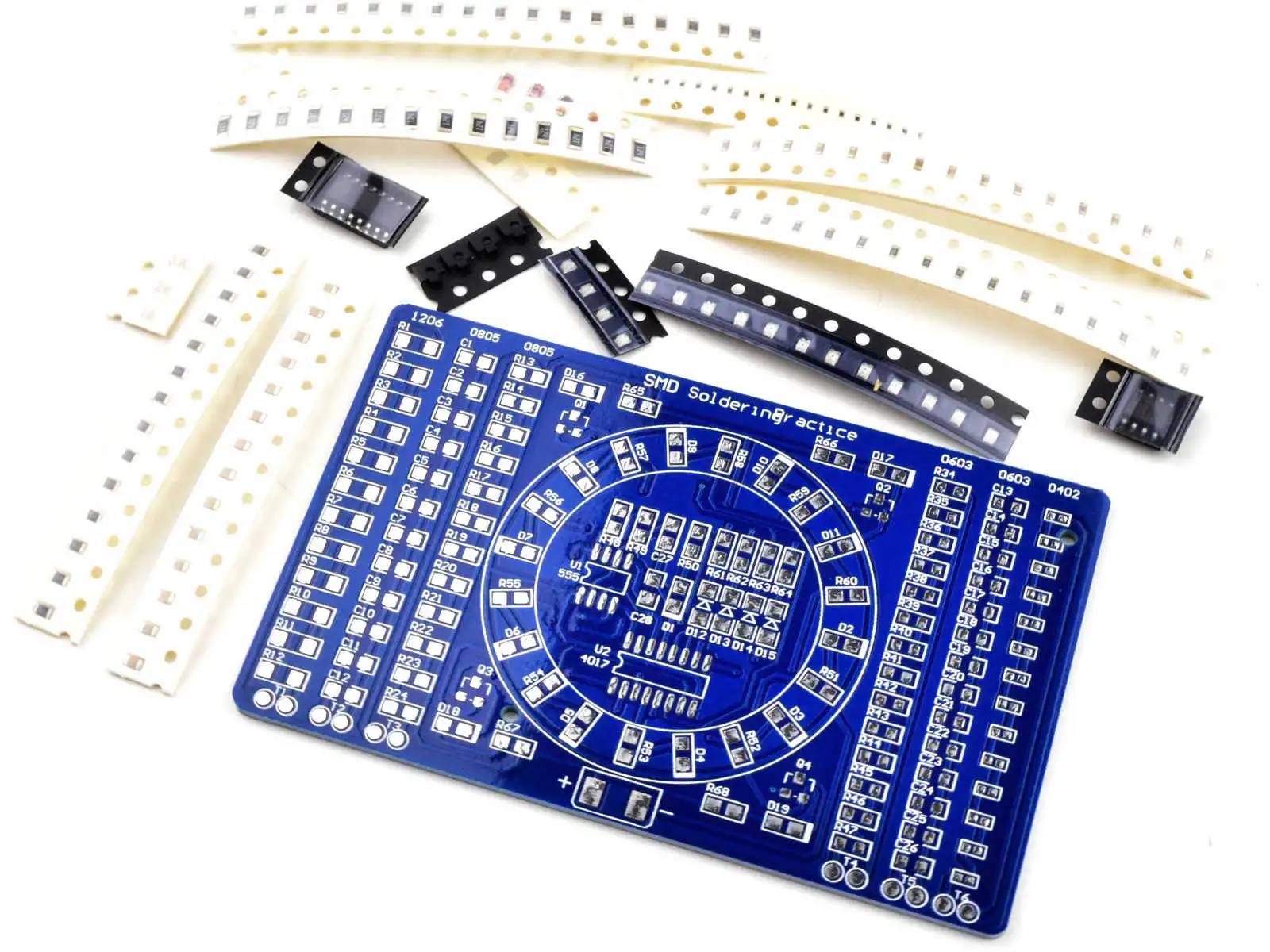
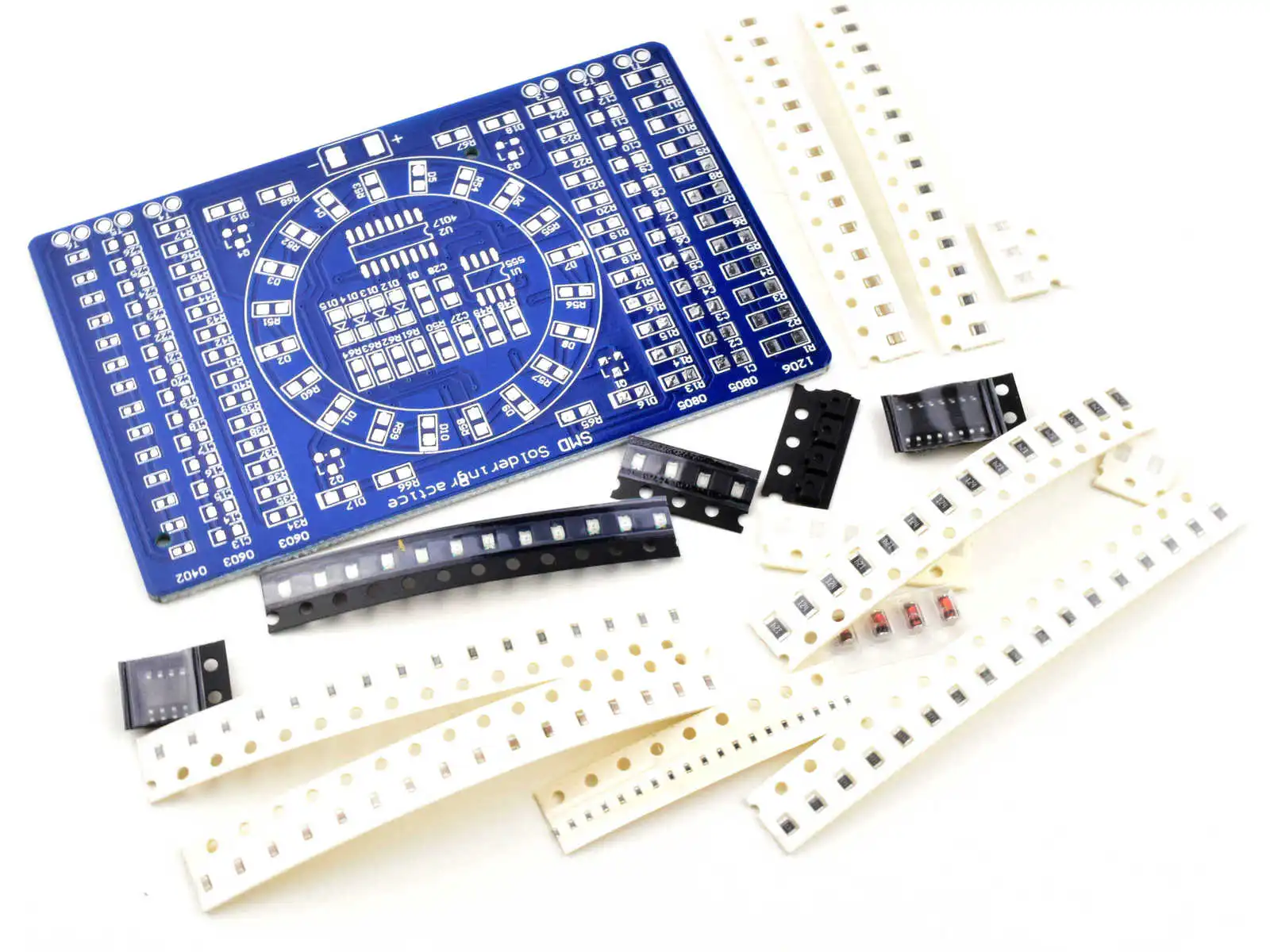
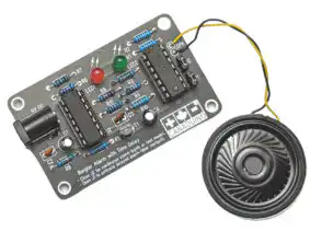
SMD soldering exercise kit designed for training and practice with surface-mount technology (SMT) components. This kit provides a low-cost way to build experience with different package sizes before working on valuable prototypes.
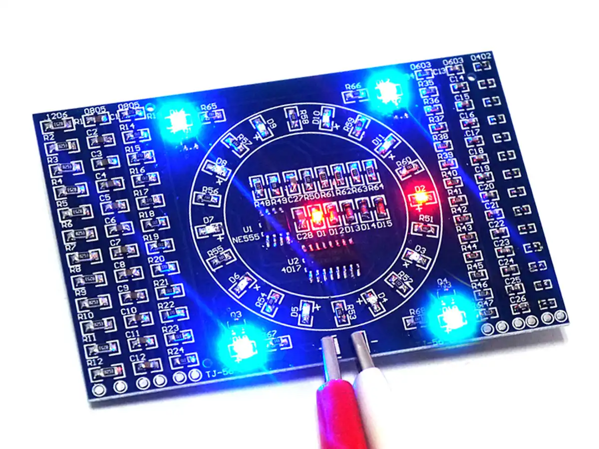
Once assembled and powered with 3-12 V DC, the circuit produces a rotating LED light effect, confirming proper assembly and soldering.
Kit contents:
- Printed circuit board
- About 100 passive components (resistors and capacitors) in sizes 0402, 0603, 0805, and 1206
- 2 integrated circuits
- Multiple LEDs and diodes
Specifications:
- Over 270 solder joints required
- Assembly time: approximately 30-90 minutes depending on skill level
- Recommended tools: soldering pen with 0.3-0.6 mm tip and solder wire 0.5-0.8 mm diameter
This exercise demonstrates the varying difficulty of SMD soldering:
- 1206 and 0805 packages are relatively easy
- 0603 parts require more precision
- 0402 components present a real challenge
Completing this kit provides a solid foundation for moving on to real SMD projects with confidence.


paul.lancaster (verified owner) –
This is a good kit for those of us who want to practice a number of different ways to solder SMDs and to get some safe exposure to the smaller packages. You will need a fine conical solder tip, fine wire solder, a strong magnifier and light, sharp tweezers, and a flux pen/syringe (not to mention steady hands!) to be successful. You also want to work on a desk material that you can see the SMDs on as you will drop them and will likely have to search for the smaller ones. I looked at a number of different videos on you-tube to see different methods for soldering SMDs and tried them all so I could pick what seems to work for me. I also discovered that rework seemed to be much harder than with through hole.
Since the instructions are all in Chinese between Google translate and my experience here is my version of them:
1. The board is divided into the left 3 columns, the centre section, and the right 3 columns. The columns are for practice only with various package sizes of supplied components which are of a non-specific value and may be only resisters despite some columns being marked for capacitors as the soldering techniques are the same for these components. You will note that you can see if you successfully soldered a column by measuring on the test pads at the bottom of each as they are wired in series. Note that the packaging size of the components are indicated at the top of each column. Start on the left columns and the larger components and work right to the tiny 0402 packaging.
2. For the centre section note that LED polarity is marked on the circuit board by a thicker white printed boarder representing the negative electrode. The LED polarity on the SMD is marked on the underside of the SMD LED. When complete the centre section is powered by 3V – 12V and the LEDs will flash on in a timed sequence so you know you were successful.
3. For some components spares are supplied.
4. Components for the centre section:
R50, R51-R60, R65-R68 – Res 1K marked 102
D1, D2-D11, D16-D19 – LED
Q1-Q4 – Trans J3Y
D12-D15 – diode 4148
R48, R61-R64 – Res 10K marked 103
R49 – Res 2M marked 205
C27, C28 – 0.1µF Cap
U1 – IC 555
U2 – IC 4017